Characterization of component interactions in two-stage axial turbine
Abstract
This study concerns the characterization of both the steady and unsteady flows and the analysis of stator/rotor interactions of a two-stage axial turbine. The predicted aerodynamic performances show noticeable differences when simulating the turbine stages simultaneously or separately. By considering the multi-blade per row and the scaling technique, the Computational fluid dynamics (CFD) produced better results concerning the effect of pitchwise positions between vanes and blades. The recorded pressure fluctuations exhibit a high unsteadiness characterized by a space–time periodicity described by a double Fourier decomposition. The Fast Fourier Transform FFT analysis of the static pressure fluctuations recorded at different interfaces reveals the existence of principal harmonics and their multiples, and each lobed structure of pressure wave corresponds to the number of vane/blade count. The potential effect is seen to propagate both upstream and downstream of each blade row and becomes accentuated at low mass flow rates. Between vanes and blades, the potential effect is seen to dominate the quasi totality of blade span, while downstream the blades this effect seems to dominate from hub to mid span. Near the shroud the prevailing effect is rather linked to the blade tip flow structure.
1. Introduction
Axial turbines of modern aero-engines are designed at high loading factors, hence leading to inherently complex flows which are in essence unsteady owing to the relative motion between nozzle guide vanes (NGV) and rotor blades. Each row generates non-uniformities in the downstream flow field due to potential and viscous effects which are ingested by the following vanes/blades’ rows. Among the most important non-uniformities in the case of hp turbines are wakes, secondary flows, shocks and hot-streaks. Early flow models used simplifying assumptions such as the through-flow1 methods neglecting the circumferential variations and unsteadiness related to the relative motion between rotating and stationary parts. After advents of CFD tools, and since experiments are cumbersome and in many cases impossible, it has become presumably possible to predict the details of flow structures and direct investigations towards the most challenging unsteady phenomena, especially the stator/rotor interactions.
The flow computations based on one blade per row is still used when predicting the turbomachinery performance. However, Dieter and Jing2 have concluded that with a computational domain restricted to one blade, there is a variation in the turbine stage efficiency about 0.52% among different clocking positions. Therefore, there is still a need for reducing the computational domain in multi-component machinery without affecting too much the flow physics. In this issue many workers accounted for the non-integral blade counts, such as Erdos et al.3 who first developed the “phase lagged method” to compensate for the non-integral blade counts without modeling the entire blades rows. Adamczyk4 after introducing the mixing-plane method5 proposed the average-passage method in which the rotor domain is expanded upstream and downstream. Giles6 modified the “phase lagged method” and eliminated the assumption of temporal periodicity by using the time inclined computational plane. A way of calculating rotor-wake interaction is to use ordinary unsteady CFD with the time lagged periodic boundary condition, i.e., the chorochronic periodicity7, 8 and the Fourier representation near periodic boundaries. Gerolymos et al.8 gave a detailed analysis of the chorochronic periodicity and proposed a new methodology for predicting the unsteady aerodynamics of the interactions between two blade rows based on Fourier series both in time and circumferential direction. By comparing with the measurements made for a 1.5 stage turbine, the ability of this technique in studying stator/rotor interactions was clearly shown. Miller et al.9 studied the interaction of an hp transonic turbine stage followed by an intermediate vane, focusing on the upstream potential effects of the vanes on the rotor blades, which seemed to be only affected downstream the throat. Later, Miller et al.10 described accurately the flow structure of vane and the shock/wake interaction and migration of flow across the rotor and the interference of both rotor and second vane potential fields on the coming flow.
Rai and Madavan11 concentrated their study on the scaling technique to overcome the problem of non-integral blade counts by scaling the blade pitch while maintaining a constant solidity ratio. Arnone and Pacciani12 carried out the domain scaling technique for a two-stage transonic turbine having 22 vanes and 38 blades. The scaled configurations were successively: 1/2 (scaling ratio 0.87), 3/5 (scaling ratio 1.036), 4/7 (scaling ratio 0.987) and 7/12 (scaling ratio 1.0076). Their conclusion is that the 1/2 configuration led to a premature choking in the rotor passages and the pressure distributions were significantly affected, but these effects were largely reduced in the 3/5 configuration and even nonexistent in the 4/7 configuration. Clark et al.13 and Yao et al.14 have shown the importance of modeling the actual blade counts in multi-stage simulations for accurate predictions of the entropy migration and the frequency spectrum resulting from stator/rotor interactions. Clark et al.13 investigated the effect of blade count and scaling on the unsteady pressure field for a configuration of an axial turbine representative of a modern design, consisting of 36 vanes and 56 blades of the hp stage and 36 vanes of the lp stage. They showed that as the scaling was used (holding the mid-span axial gap) to reduce the computational domain to only 2 vanes and 3 blades for the first stage and 2 vanes for the second stage (1/18th of wheel), errors in the unsteady pressure amplitudes could arise. Also Yao et al.14, based on simulations for a 1.5 stage axial turbine of vane/blade counts 36, 41 and 36, showed that for the configurations 6/7/6 (scaling ratio 0.9762) and 1/1/1 (scaling ratio 1.14), the time-averaged pressure distributions over the vanes and blades were not significantly affected, and concluded that the scaling ratio should be kept close to unity. He and Chen15 applied the unsteady Navier–Stokes equations to analyze the stator/rotor interactions in an axial turbine with 32 vanes and 48 blades, and concluded that the computational domain consisting of 2 vanes and 3 blades produced unsteady pressures that were compared well with the experimental data. The aforementioned studies showed a veritable challenge for the CFD codes in providing acceptable details of the main flow features, especially the stator/rotor interactions which involves the potential interaction propagating both upstream and downstream. The magnitude of this effect depends on the Mach number and the axial inter-distance. Unlike the potential influence, the blade wake is only convected downstream and the static pressure does not vary significantly. In the transonic regime, shock structure provokes intense unsteady effects. The most significant contribution to unsteadiness is the periodic chopping of wakes16 and secondary flow vortices from the upstream blade row by the downstream blade row.17, 18 Also the interactions of convected secondary flow vortex/tip leakage vortex with the periodic wake or potential field should be considered. According to the literature there are few published works on the unsteady interactions between leakage flows and adjacent vane/blade rows in axial turbines. Behr et al.19 have indicated that the pressure field of the second vane has an influence on the development of tip leakage vortex of the rotor. Qi and Zhou [20] performed an experimental and a numerical investigation in the blade tip region and concluded that the upstream wakes are shown to reduce the strength of the tip leakage vortex, and owing to the unsteady effects of wakes there is appearance of counter-rotating vortex pairs within the tip leakage vortices which cause a significant pressure fluctuation.
This study concerns the determination of aerodynamic performance of an hp two-stage axial turbine and the analysis of stator/rotor interactions by means of the code Ansys-CFX. Because the computing power was very limited, the technique of domain scaling was applied to reduce the computational domain and grid size. This latter required a careful treatment for the blade profiles and aspect ratio while adopting a scaling ratio close to unity in order to conserve the physical periodicity and not altering too much the aerodynamic performance. The fluctuations of static pressure were recorded at different points and lines and the FFT was used to analyze the flow unsteadiness characterized by a space–time periodicity, leading to the determination of different frequencies and spatial modes characterizing these interactions.
2. Geometry and computation grids
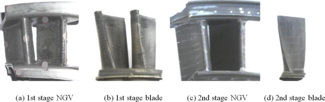
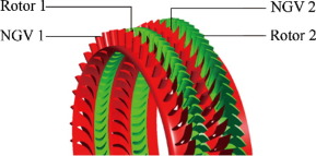
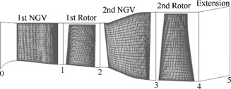
This two-stage hp axial turbine (Fig. 1) drives an hp compressor of an old turbofan engine. The determination of the geometry of the two stages vanes and blades required utilizing an optical measuring machine equipped with a contact-less optical feeler and a three-jaw chuck to rotate and sweep the totality of measured surfaces. The main data are given in Table 1 and the CAD models are shown by Fig. 2.
Download: Download full-size image
Fig. 1
Table 1. Main characteristics of hp two-stage axial turbine.
Characteristics
Dimension (mm)
1st NGV
1st rotor
2nd NGV
2nd rotor
Blade count
46
80
56
74
Inlet hub diameter
737
727
720
686
Inlet shroud diameter
836
836
836
864
Outlet hub diameter
727
720
686
682
Outlet shroud diameter
836
836
864
864
Average blade height
52
56.25
73.5
90
Tip clearance
2.146
2.146
Download: Download full-size image
Fig. 2
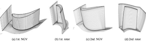
The grids of the vanes and rotor blades required the topology of different blocks to be arranged in regular (structured) and irregular (unstructured) patches meshed by hexahedral elements with an H-grid type at leading edge and J-grid at trailing edge. An O-grid guaranteed near-orthogonal elements and a better resolution of boundary layers around vanes and blades and a clustering near the hub and blade tip allowing a good resolution of the flow gradients and the vortical structures. Local refinements to boundary layers required values of y+ compatible with the turbulence model k–ω SST which has been validated in various turbomachinery applications and produced excellent results, particularly with regard to flow separations. The near wall distance was estimated based on the first node distance21
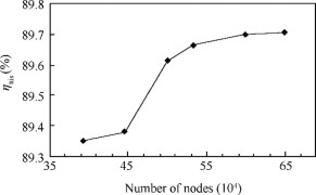
and to cover regions of high Reynolds number, the maximum of flow velocity was used. After a preliminary assessment of grid refinements under the nominal operating conditions, corrections for the near wall distances were made and the steady simulations were repeated to assess the final quality of the grids. To study the dependency of flow solution on the mesh sizes, the total-to-total isentropic efficiency ηttis is plotted (Fig. 3) against six grid sizes, showing a stability of solution above a grid size of 653,344 nodes which was considered for the next computations. The different grids are presented in Fig. 4 and the meridional view is shown by Fig. 5.
Download: Download full-size image
Fig. 3
Download: Download full-size image
Fig. 4
Download: Download full-size image
Fig. 5
3. Steady flow simulations
The steady flow simulations were carried out by means of the code Ansys-CFX, under the operating conditions corresponding to averaged inlet total pressure Pt0 = 2,841,460 Pa and temperature Tt0 = 1510 K, while the rotational speed was varied around the nominal value of 9823 rpm.22 The frozen rotor interface is useful when the circumferential variations of flow properties are large. In such an interface, the stationary and rotating frames are connected so that each sliding interface has a fixed relative position for producing the steady solution to the multiple frames and accounting for interactions between them. The stage interface appropriately used in predicting the aerodynamic performance does not require the interfaces to be identical on both sides, and the averaging incurs a one-time mixing loss equivalent to assuming that the physical mixing supplied by the relative motion between the components is sufficiently large to cause any upstream velocity profile to mix out prior entering the downstream component.
3.1. One-blade per passage simulations
Here, the averaged inlet total pressure and temperature were imposed at inlet of first NGV and a static pressure was specified at exit of second rotor, while the periodic boundary condition applied at one pitch away of each component. The high resolution advection scheme with a local time scale factor of 10 was used for the flow simulations. The predicted aerodynamic performance maps based on the stage interface are given in terms of total-to-total isentropic efficiency ηttis and total-to-total expansion ratio πtt as function of reduced mass flow parameter